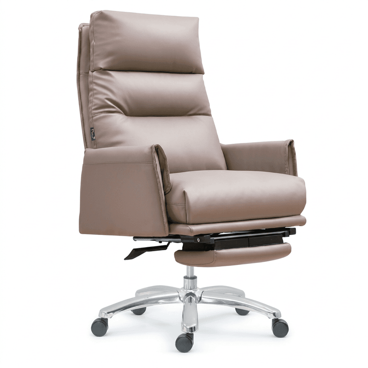
Office Chair Leg Modeling
The following ideas and methods can be referred to for office chair leg modeling:

When it comes to modeling the wheels with casters, it is necessary to first clarify the basic structure of the wheels, which usually includes the hub, tire, and connecting components. In modeling software, you can start by creating the basic shape of the hub, such as using a cylinder tool to draw the main body of the hub and adjusting its radius and height according to design requirements. For details on the hub, such as spokes, you can build them by drawing lines and stretching them into surfaces. For the tire part, you can use a rotation tool to generate a solid model of the tire by rotating a curve representing the tire's cross-section around a central axis. The connecting components are created step by step according to their actual shapes using tools such as stretching, rotating, or scanning, ensuring accurate connection relationships between components. For example, the hub and tire are fixed through appropriate connecting structures, and the connection part between the caster and the office chair leg should conform to the actual installation method.
For modeling office chair legs without casters, you can draw on the modeling ideas of casual sofa chair legs. First, determine the fixed position of the chair legs, which needs to be decided based on the overall design of the office chair and ergonomic requirements to ensure that the layout of the chair legs provides stable support. Then, proceed with the drawing design. Draw the contour lines of the chair legs in an appropriate view of the modeling software. These lines should accurately reflect the external features of the chair legs, such as the degree of curvature and changes in thickness. Surface positioning is a crucial step. Generate basic surfaces by stretching or rotating the contour lines, and then use tools such as offsetting and trimming to adjust the positions and shapes of the surfaces to meet design requirements. In terms of thickness treatment, add an appropriate thickness to the basic surfaces according to the material of the chair legs and actual needs, which can be achieved through extrusion or thickening commands. Subdivision surface operations can make the surface of the chair legs smoother and more natural, enhancing the texture of the model. Body block generation involves combining the various parts into a complete chair leg model, paying attention to the connection and transition between body blocks. Scaling adjustments are used to ensure that the dimensions of the chair legs conform to the overall design proportions. Line drawing can further refine the decorative or structural lines on the chair legs. Finally, convert these lines into solid structures through stretching and other operations to complete the model of the chair legs.