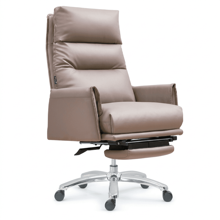
Office Chair Engineering Construction Process Diagram
Currently, a complete 'Office Chair Engineering Construction Process Diagram' has not been directly found, but the requirement can be met through a combination of the following resources:

I. CAD Drawing Resource References
Italian Chair CAD Construction Drawings
The Hongdong China Material Network (ID: 1210166718) offers CAD drawings of Italian chairs for download, including structural breakdown diagrams and dimensional annotations for components such as the backrest, seat, and armrests. These drawings can assist in understanding the frame design logic of office chairs, such as the welding joints of metal supports and the mortise-and-tenon connections of wooden components. If the office chair is of Italian style, its streamlined design details can be directly referenced; for other styles, the general structural framework can be extracted and modified.Office Furniture CAD Drawing Library
The Civil Engineering Online platform provides detailed node diagrams of office chairs, covering assembly relationship diagrams of key components such as chair wheels, pneumatic rods, and five-star bases, as well as soft-pack structure breakdowns from American furniture CAD blocks. These drawings can clarify the functional module division of office chairs, such as the connection method between the pneumatic rod for height adjustment and the seat, and the rotating mechanism design between the chair wheels and the five-star base, providing a structural foundation for the construction process diagram.
II. Construction Process Description References
Fully Upholstered Table and Chair Construction Process
This process details the base material treatment (such as moisture-proof treatment of wooden frames), sponge lamination (thickness matching and bonding methods of multi-layer sponges), fabric fixation (applicable scenarios for nail gun fixation or Velcro粘贴 (here should be 'Velcro attachment')), and corner treatment (how to avoid fabric wrinkles) of upholstered components. The upholstered parts of office chairs, such as the seat and backrest, can directly apply this process, for example:- The seat sponge adopts a composite structure of 3cm high-density sponge + 2cm memory foam to enhance comfort.
- When fixing the fabric, reserve a 5-8mm allowance at the corners and secure it with hot melt adhesive or special clamps to ensure flatness.
Metal/Plastic Component Processing Techniques
If the office chair includes metal supports or plastic shells, refer to the general techniques of sheet metal processing (cutting, bending, welding) or injection molding (mold design, draft angle control). For example, the metal support of the five-star base needs to undergo surface sandblasting treatment to enhance coating adhesion, and the plastic backrest needs to be designed with reinforcing ribs in the mold to improve structural strength.
III. Suggestions for Drawing Process Diagrams
- Layered Display: Decompose the office chair into the frame layer (metal/wooden structure), upholstered layer (sponge + fabric), and functional layer (pneumatic rod, chair wheels), and draw sectional views or exploded views respectively.
- Annotate Key Parameters: Clearly specify material specifications (such as sponge density, fabric material), connection methods (such as mortise-and-tenon, welding, screw fixation), and dimensional tolerances (such as backrest inclination angle ±1°) in the drawings.
- Combine with Process Descriptions: Annotate construction points beside the drawings, such as 'Chair wheels should be installed using M6 screws with a torque controlled between 3-4N·m' to ensure consistency between the drawings and process guidance.
By integrating the structural details of CAD drawings with the technical points of construction techniques, the drawing of the office chair engineering construction process diagram can be systematically completed.