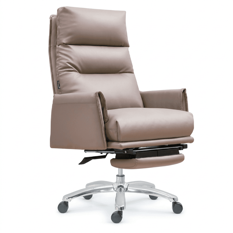
Office Chair Disassembly Display
The display of office chair disassembly can be carried out by gradually disassembling from the whole to the parts, or by classifying and displaying according to the structure of ergonomic chairs. The specific steps are as follows:

I. Disassembly Display by Disassembly Sequence
Separate the Seat and Backrest
First, locate the connecting screws between the seat and the backrest, which are usually located at the junction of the lower part of the backrest and the seat. Use a screwdriver to unscrew the fixing screws, and then the two can be separated. If it is an integrated backrest (such as some ergonomic chairs), this step is not required, and you can directly proceed to the next step.Remove the Armrests
The armrests are generally fixed to both sides of the seat with screws. Locate the screw positions (mostly on the inner side or bottom of the contact surface between the armrests and the seat), and use a screwdriver to unscrew them. Then the armrests can be removed. Some armrests may use a snap-fit design, and a tool is required to gently pry open the snaps to unlock them.Separate the Gas Lift and Base
Completely invert the chair and observe the connection part between the gas lift and the base. If it is fixed by a snap spring, use needle-nose pliers or a special tool to loosen the snap spring; if it is fixed by screws, unscrew the screws and then pull the gas lift straight up. For a hydraulic lift rod (such as in a lifting chair), first remove the base: tap around the bottom steel ring with a rubber mallet, and then pry the base to make it detach; then remove the screws on the upper seat, tap the metal base with a hammer, and step on the hydraulic lift rod with your foot to assist in separation.Remove the Casters
The casters are usually directly snapped into the caster seats on the base. You can pull them out directly by hand, or use a screwdriver to gently pry the edges of the casters to separate them from the caster seats. If the casters are tight, you can appropriately heat them (such as with a hot air gun) to make the snaps expand and then remove them.
II. Disassembly Display by Structure Classification
The structure of an ergonomic chair can be divided into the following parts, which are displayed by category after disassembly:
- Backrest: Includes the main back frame and adjusting mechanisms (such as tilt-lock devices).
- Lumbar Support: An independent support module or designed integrally with the backrest.
- Headrest: Connected to the backrest via a bracket, detachable or height-adjustable.
- Seat Cushion: Contains a sponge or mesh fabric filling layer, and some are integrated with the base.
- Armrests: Divided into fixed types and adjustable (height/rotation) types, and the adjusting components need to be disassembled separately.
- Base: The core component that integrates tilt and lift functions, and needs to be displayed after being separated from the gas lift.
- Gas Cylinder: Marked with safety certification logos (such as SGS, BIFMA), displayed separately to emphasize safety.
- Five-Star Base: Made of metal or plastic, and the overall structure is displayed after removing the casters.
Precautions: Take a photo of the whole chair before disassembly to record the connection methods of each part; use appropriate tools to avoid damaging the threads or snaps; release the internal pressure of hydraulic components during disassembly to prevent accidental ejection.